All posts by gebapps@gmail.com

frankennxtbuild

FrankenNXT – A Frankenstein Story

I rescued an old Lego NXT robot from the dump.  Someone thought that an old pile of parts like this had no value.
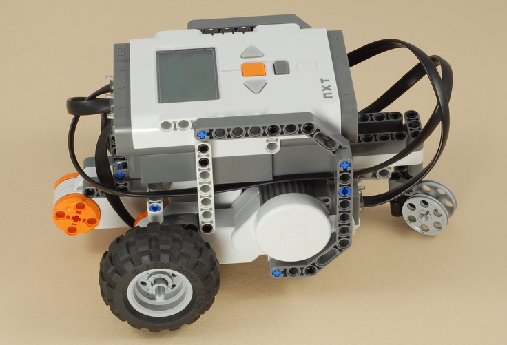
After cleaning it up and inserting new batteries, not surprisingly, the brick would not power up. The electronics were dead.
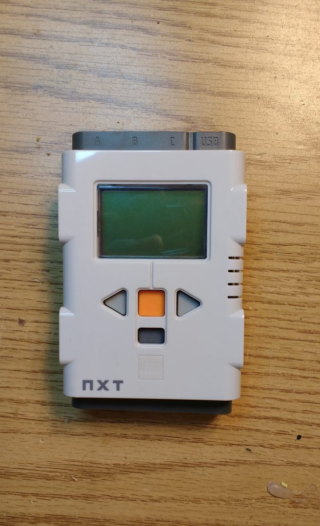
The good news was that the three motors were working fine, so I set about turning this old corpse from the bone yard into a robot again.

I stripped the broken brick for parts.
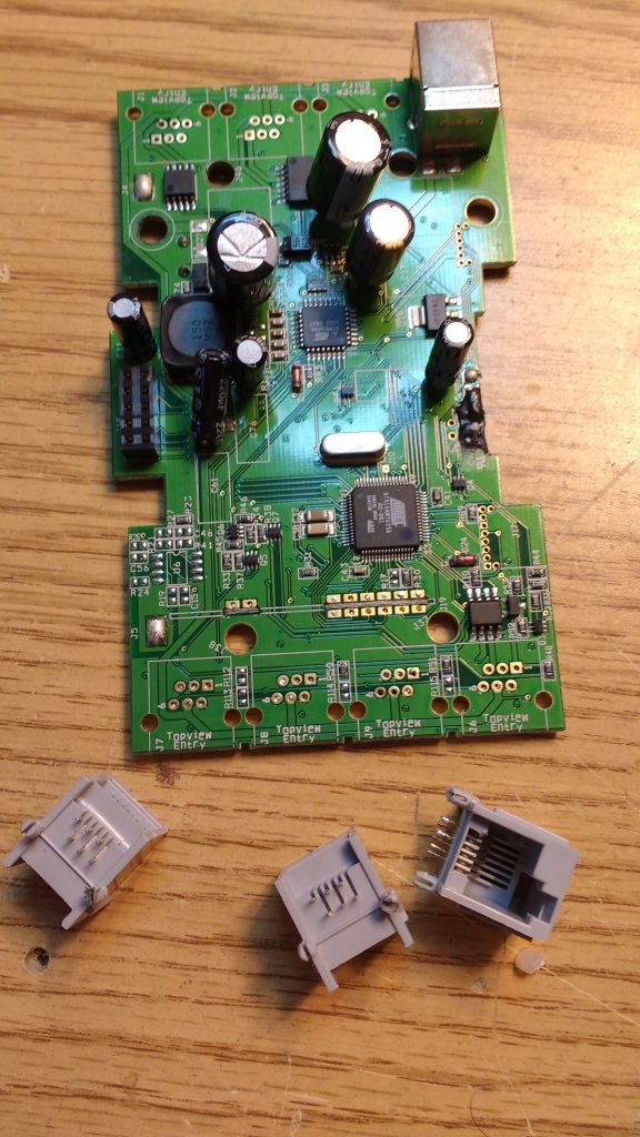
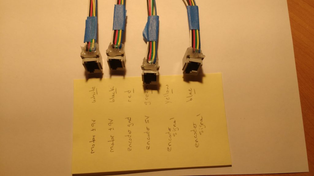
I soldered wires to the terminal connectors.  I then encased each one in a bit of hot glue so the delicate connections would not break.
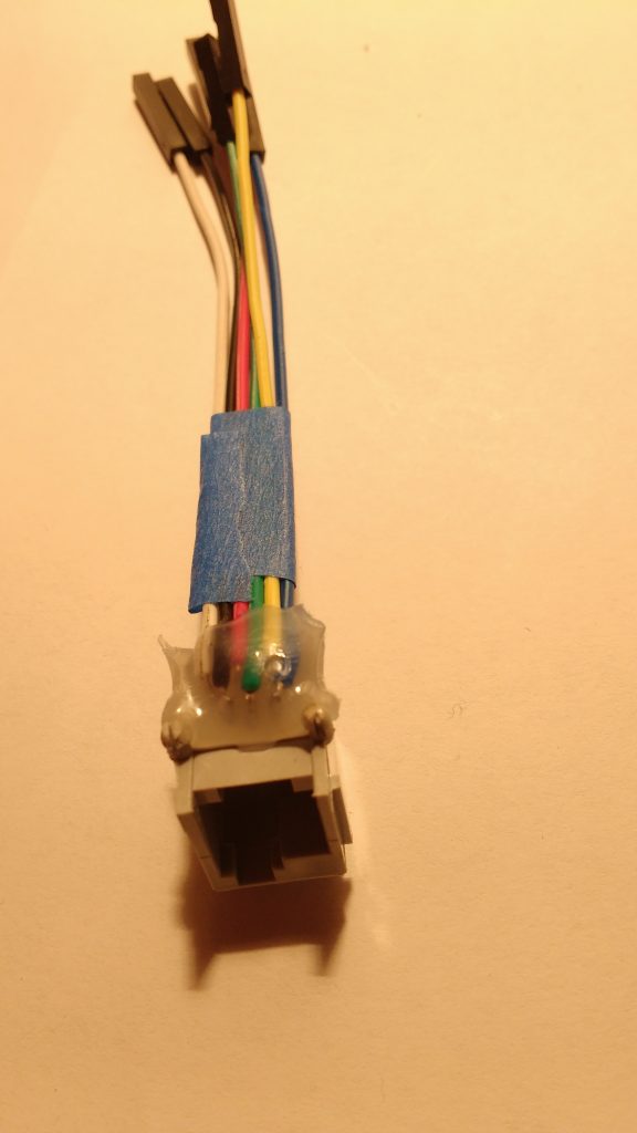
The motor connectors use all six wires.  Motor positive and ground, rotary encoder 5V and ground, and two rotary encoder signal wires.
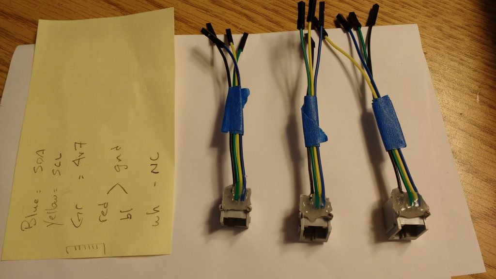
The sensor connectors use only four wires.  Two wires are I2C data and clock, and the other two are I2C device 5V and ground.
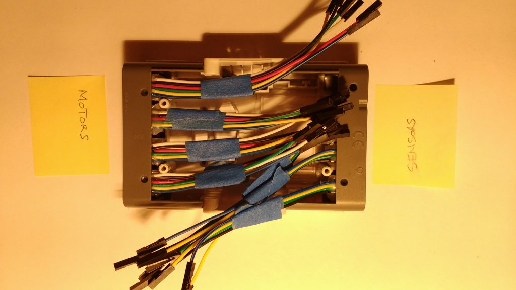
The connectors fit back into the empty shell of the original brick.
I plugged everything into a bread board to check power consumption and otherwise debug the system.
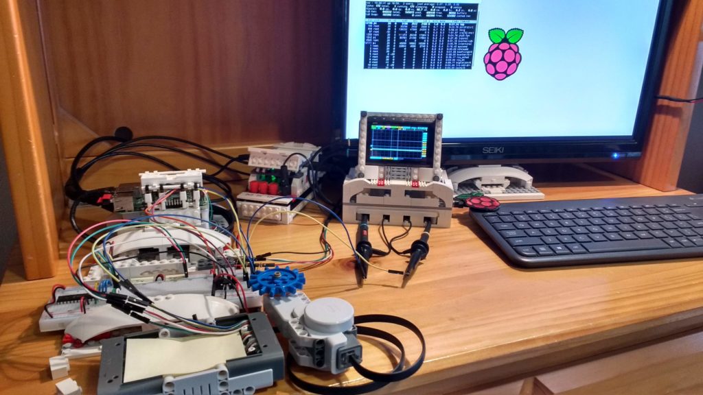
After confirming that I could turn the motors and nothing was on fire, I worked on getting it assembled and into the case. I had to make room for a buck converter to step down the 9V from 6 AA batteries to  the 5V required to run the Raspberry Pi and power the I2C devices in the sensor ports.
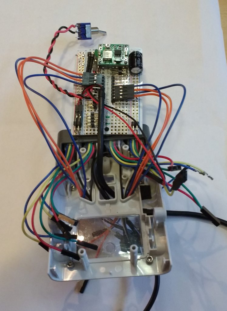
A voltage divider is required to get the 5V motor encoder signal down to the 3V3 used by the Raspberry Pi GPIO.  This is a simple matter of including two resistors in the circuit for each of the motor encoder signal wires.
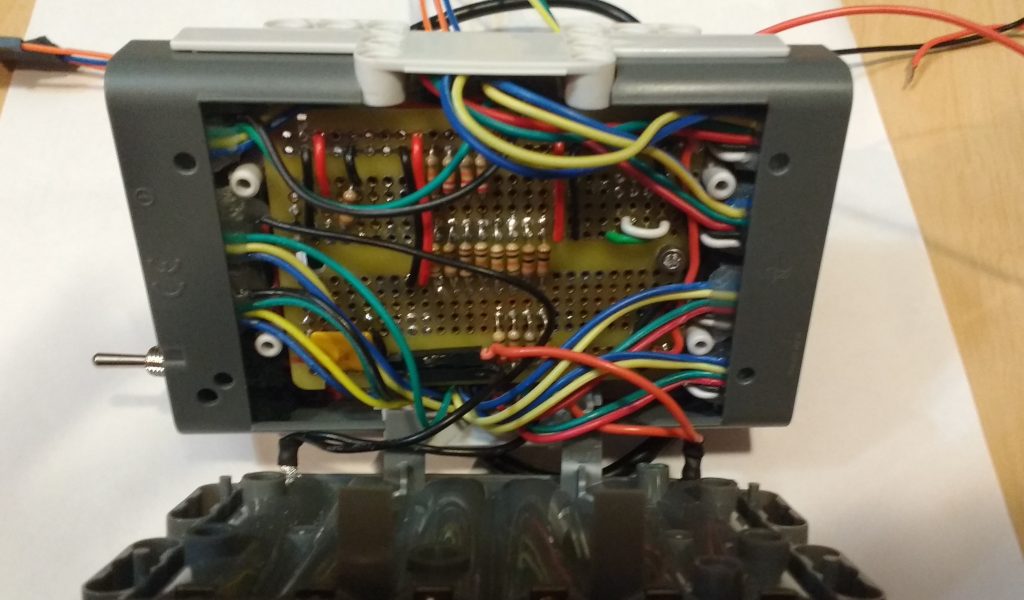
I somehow managed to wiggle all the wires into place and everything fit inside the NXT brick shell.
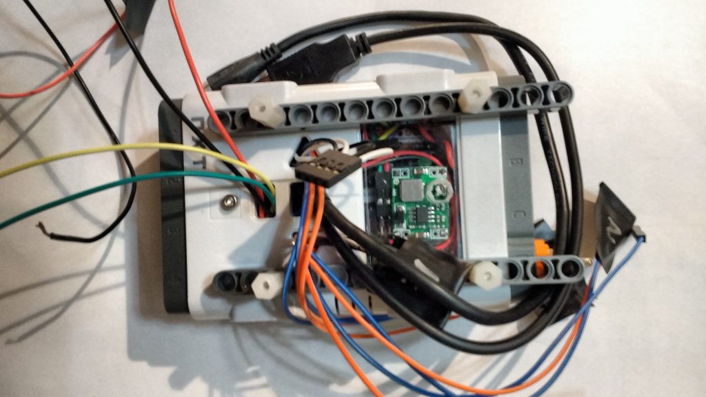
I replaced the brain with a Raspberry pi and an Adafruit motor hat.
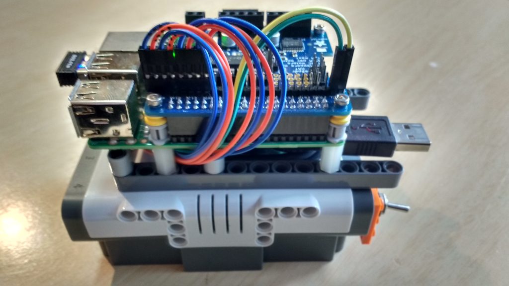
The Adafruit motor hat has a bit of space for extra connections, so I added a MCP23008 chip to provide an additional 8 input/output pins. I also included four additional connectors for I2C devices.
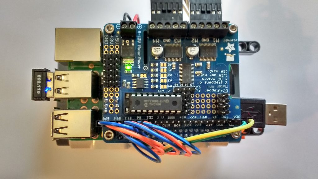
I energized the system with 1.21 gigawatts in the dead of a stormy night.
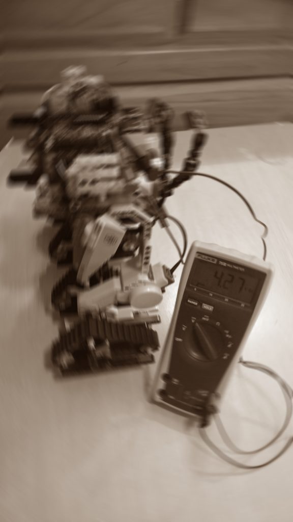
FrakenNXT was born.
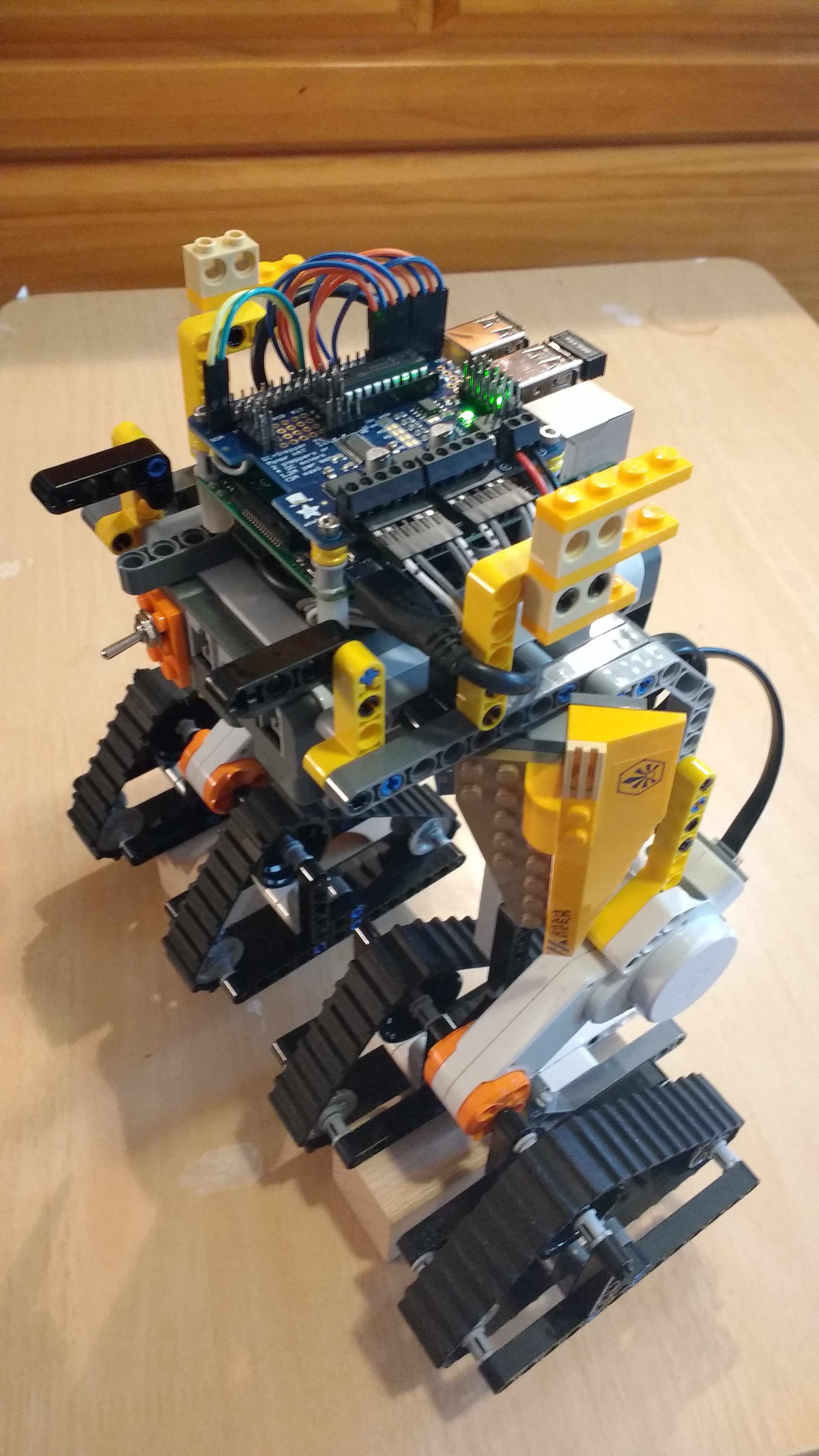
I wanted to show off my creation, so the kids and I went on to build a Lego Chima themed robot on the frame (it so happened that we had a lot of Chima sets around from when the kids were younger).

We took it to the Bricks Cascade Lego convention in Portland Oregon, and put it on display with some of our other robotic creations.
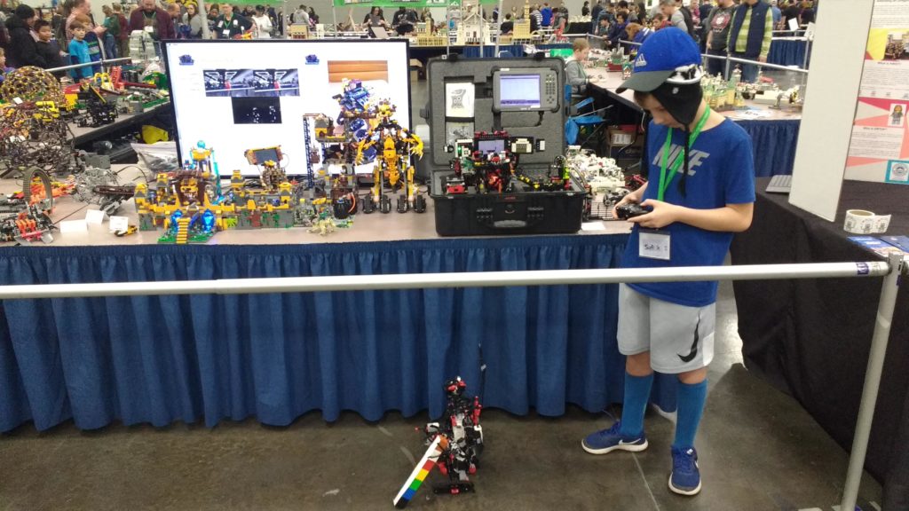
Alexander driving the EV3 robot while FrankenNXT with motion sensor camera looks on.

A Raspberry Pi camera was added for a simple motion detection demonstration.

See our FrankenNXT page for details about the software we wrote to control the robot with an Xbox joystick

gpiojoyfunctions

GPIO Joy User Functions

If you need to do something more complex than simple device control with the joystick, you can write your own functions and map them to joysticks or buttons on the controller.

<GpioConfig>

  <JoystickFunctions>

    <!--  Declare one or more assemblies to load.  -->
    <!--  You can call one or more setup functions at load time.  -->
    <Assembly>
      <Name>MyUserFunctions.dll</Name>
      <Setup class="MyUserFunctions.UserFunctions">Init</Setup>
    </Assembly>

    <!--  Map your function to a joystick button  -->
    <Function>
      <Joystick>DpadUp</Joystick>
      <Method assembly="MyUserFunctions.dll" class="MyUserFunctions.UserFunctions">SomeFunction</Method>
      <Name>My Func</Name>
    </Function>

  </JoystickFunctions>

</GpioConfig>

To integrate your own assembly with GPIOJoy:

  • Create a C# assembly using .NET Framework 4.7.2
  • Create one or more static classes with your user functions.
  • Add a reference GpioJoy.exe if you want to use pins or GPIO devices from your user functions.
    • You can use pins or devices in your functions by using the GpioJoyProgram.PinManager property

For example the following code could be used to turn pin 40 on and off five times when you hit a controller button.

namespace MyUserFunctions
{
    public static class UserFunctions
    {
        //  To use pins in your user functions, add a reference to GpioJoy, GpioManagerObjects, and wiringGpioExtensions
        static GpioManager PinManager => GpioJoyProgram.PinManager;

        public static void Init()
        {
            Console.WriteLine("User functions, init called");
        }


        public static async void SomeFunction(bool input)
        {
            //  check for button mashing, only accept this button once every six seconds
            if ( input && Environment.TickCount - _buttonDownSomeFunction > 6000)
            {
                await FlashButtonFourty();
            }
        }
        static int _buttonDownSomeFunction = 0;


        /// <summary>
        /// Flash pin 40 five times
        /// </summary>
        static async Task FlashButtonFourty()
        {
            for (int i = 0; i < 5; i++)
            {
                PinManager.GetPin(40).Write(1);
                await Task.Delay(500);
                PinManager.GetPin(40).Write(0);
                await Task.Delay(500);
            }
        }
    }
}

gpiojoyexpension

GPIO Joy Port Expansion Chips

The Raspberry Pi has 17 general use GPIO pins. When this is not enough for your creation, you can use a pin expansion chip.  You can use the MCP port expansion chip for simple output. You can use the PCA port expansion chip for hardware PWM output.

This example shows how to configure a MCP23008 (8 extra pins) and a MCP23017 (16 extra pins) to with a pin base starting at 200.

<GpioConfig>

  <MCPs>

    <MCP>
      <Type>Mcp23008</Type>
      <!-- chip at 0x20-->
      <Address>32</Address>
      <Base>200</Base>
    </MCP>
    <MCP>
      <Type>Mcp23017</Type>
      <!--  chip at 0x21 -->
      <Address>33</Address>
      <Base>208</Base>
    </MCP>

  </MCPs>

  <PinModes>

    <!-- Pin 0 on MCP23008 -->
    <Pin>
      <Number>200</Number>
      <Mode>Output</Mode>
    </Pin>
    <!-- Pin 0 on MCP23017-->
    <Pin>
      <Number>208</Number>
      <Mode>Output</Mode>
    </Pin>

  </PinModes>

</GpioConfig>

This example shows how to configure a PCA9685 chip when using the Adafruit Servo Hat. The first pin  is configured to drive a servo motor forward and backward with the XBox left stick.  The second pin is configured for and simple PWM output on the right stick up.

<GpioConfig>

  <PCAs>

    <PCA>
      <!-- adafruit pwm hat at default address 0x40-->
      <Address>64</Address>
      <Base>300</Base>
      <Frequency>50</Frequency>
    </PCA>

  </PCAs>

  <PinModes>

    <Pin>
      <Name>Servo One</Name>
      <Number>300</Number>
      <Mode>PWMOutput</Mode>
      <Joystick servo="true" direction="1">LeftStickUp</Joystick>
      <Joystick servo="true" direction="-1">LeftStickDown</Joystick>
    </Pin>

    <Pin>
      <Name>Green</Name>
      <Number>301</Number>
      <Mode>PWMOutput</Mode>
      <Joystick>RightStickUp</Joystick>
    </Pin>

  </PinModes>

</GpioConfig>

This example shows how to configure a PCA9685 chip when using the Adafruit Motor Hat with a motor connected to the M4 terminals.

<GpioConfig>

  <PCAs>

    <PCA>
      <!-- adafruit motor hat at default address 0x60-->
      <Address>96</Address>
      <Base>400</Base>
      <Frequency>50</Frequency>
    </PCA>

  </PCAs>

  <PinModes>


    <Pin>
      <Number>407</Number>
      <Mode>PWMOutput</Mode>
    </Pin>

    <Pin>
      <Number>405</Number>
      <Mode>Output</Mode>
    </Pin>

    <Pin>
      <Number>406</Number>
      <Mode>Output</Mode>
    </Pin>

  </PinModes>

  <HBridgeMotors>

    <HBridgeMotor>
      <Name>M4 on Motor Hat</Name>
      <HBridge>407,405,406</HBridge>
      <Joystick direction="-1" scale="0.4">RightTrigger</Joystick>
    </HBridgeMotor>

  </HBridgeMotors>

</GpioConfig>

gpiojoysevenseg

GPIO Joy Seven Segment Display

A seven segment display is a set of LEDs arranged in the familiar ‘digital clock’ pattern.  Seven segment displays are often arranged in arrays so you can control multiple digits with fewer pins.

For example, you can control a single digit seven segment display with 9 pins.  One pin for each of the seven segments,  one for the decimal point, and one to enable or disable the digit.  You can control a pair of displays with only 10 pins, where the segment and decimal LEDs are wired to shared pins, and each display has its own enable / disable pin.

In the example below,  a three digit seven segment display is configured. The digit pins are 11,13, and 15.  The segment pins are at the bottom of the header from 29 – 40. This display is a common cathode type, so notice the negative numbers used in the <Digits> element. The display will show the value of the XBox right stick from -99 to 99 at the minimum and maximum ends of its range.

<GpioConfig>
  <PinModes>
    <!-- Digit Pins -->
    <Pin>
      <Number>11</Number>
      <Mode>Output</Mode>
    </Pin>
    <Pin>
      <Number>13</Number>
      <Mode>Output</Mode>
    </Pin>
    <Pin>
      <Number>15</Number>
      <Mode>Output</Mode>
    </Pin>
    <!-- Segment Pins-->
    <Pin>
      <Number>29</Number>
      <Mode>Output</Mode>
    </Pin>
    <Pin>
      <Number>31</Number>
      <Mode>Output</Mode>
    </Pin>
    <Pin>
      <Number>33</Number>
      <Mode>Output</Mode>
    </Pin>
    <Pin>
      <Number>35</Number>
      <Mode>Output</Mode>
    </Pin>
    <Pin>
      <Number>36</Number>
      <Mode>Output</Mode>
    </Pin>
    <Pin>
      <Number>37</Number>
      <Mode>Output</Mode>
    </Pin>
    <Pin>
      <Number>38</Number>
      <Mode>Output</Mode>
    </Pin>
    <Pin>
      <Number>40</Number>
      <Mode>Output</Mode>
    </Pin>
  </PinModes>
  <SevenSegDisplays>
    <SevenSegDisplay>
      <Name>Display</Name>
      <SegPins>33,29,36,38,40,31,35,37</SegPins>
      <Digits>-11,-13,-15</Digits>
      <Joystick direction="1">RightStickUp</Joystick>
      <Joystick direction="-1">RightStickDown</Joystick>
    </SevenSegDisplay>
  </SevenSegDisplays>
</GpioConfig>